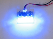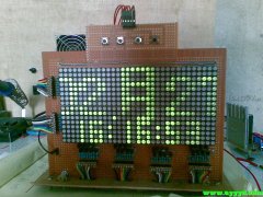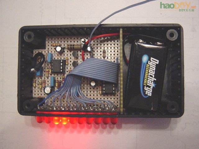
实物图
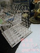
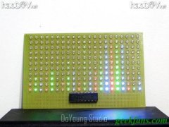
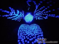
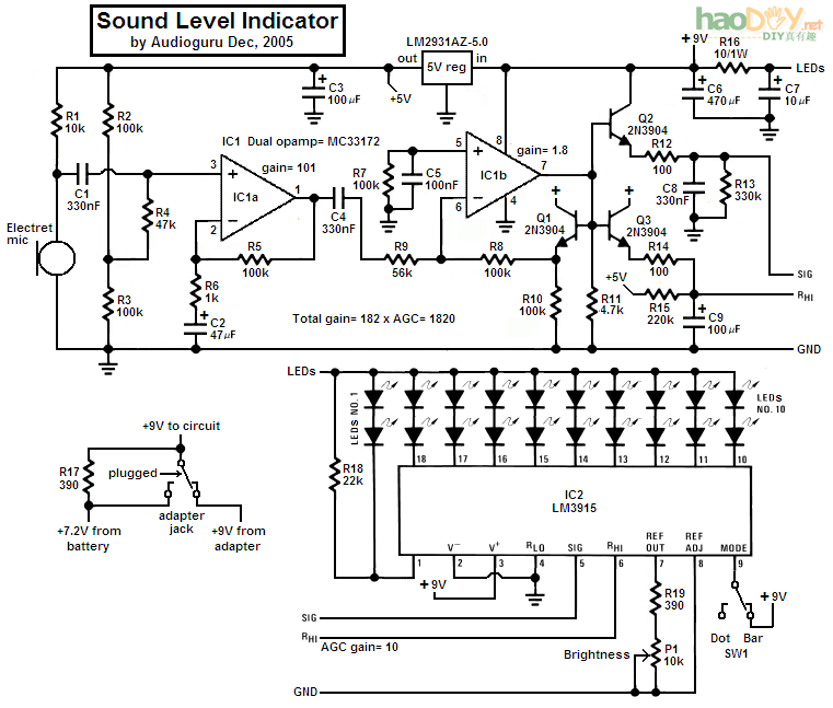 LED声压指示器电路原理图 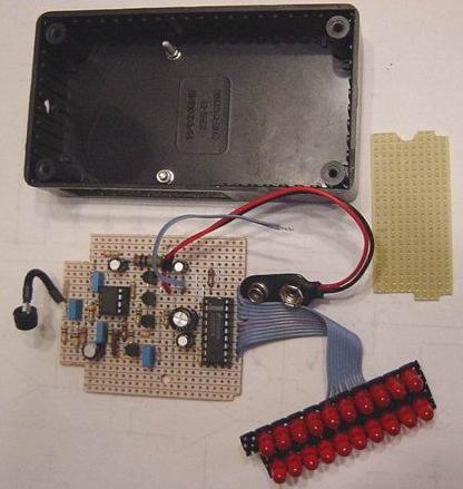 LED声压指示器安装图 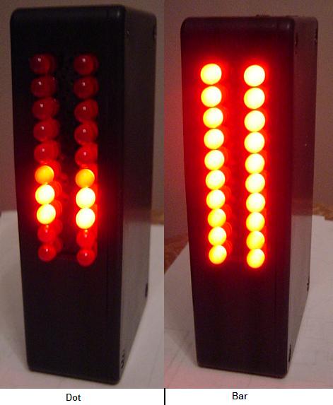 LED声压指示器 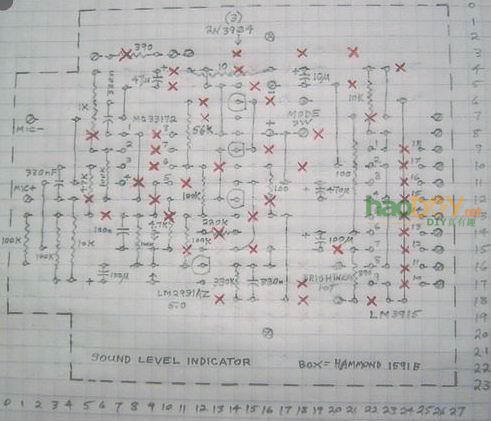 LED声压指示器面包板制作图
元件清单
R1--10k R2, R3, R5, R7, R8, R10--100k R4--47k R6--1k R9--56k R11--4.7k R12, R14--100 R13--330k R15--220k R16--10/1W R17, R19--390 R18--22k P1--10k audio-taper (log) pot C1, C4, C8--330nF C2--47uF/10V C3, C9--100uF/10V C5--100nF C6--470uF/16V C7--10uF/16V IC1--MC33172P IC2--LM3915P 5V reg--LM2931AZ5.0 LEDs--MV8191 super-red diffused Electret microphone--two-wire type Box--Hammond 1591B Battery--9V Ni-Cad or Ni-MH SW1--SPST switch Adapter jack--switched 原文: This project uses an LM3915 bar-graph IC driving two sets of ten LEDs for a 30dB range. The circuit is unique because it has an additional range of 20dB provided by an automatic gain control to allow it to be very sensitive to low sound levels but it increases its range 20dB for loud sounds. The LEDs are operating at 26mA each with the brightness control at maximum, which is very bright. The circuit has a switch to select the modes of operation: a moving dot of light, or a bar with a changing length. My prototype has a little 9V Ni-Cad rechargeable battery in it to be portable and the battery is trickle-charged when the project is powered by a 9V AC-DC adapter. #p#分页标题#e# Circuit Description 1) The electret microphone is powered by and has a load of R1 from an LM2931 5V low-dropout regulator. 2) The 1st opamp stage is an audio preamp with a gain of 101. 3) The 2nd opamp stage is a single-supply opamp which works fine with its inputs and output at ground and is used as a rectifier driver with a gain of 1.8. It is biased at ground. Since it is inverting, when its input swings negative, its output swings positive. 4) Three 2N3904 transistors are used as emitter-followers: a) Q1 is inside the negative feedback loop of the 2nd opamp as a voltage reference for the other two transistors. Hopefully the transistors match each other. b) Q2 emitter-follower transistor quickly charges C8 which discharges slower into R13 and is used as a peak detector. c) Q3 transistor is the automatic gain control. It is also a peak detector but has slower charge and discharge times. It drives the comparators’ resistor ladder in the LM3915 to determine how sensitive it is. R15 from +5V is in a voltage divider with the ladder’s total resistance of about 25k and provides the top of the ladder with about +0.51V when there is a very low sound level detected. Loud sounds cause Q3 to drive the top of the ladder to 5.1V for reduced sensitivity. #p#分页标题#e# 5) The LM3915 regulates the current for the LEDs so they don’t need current-limiting resistors. In the bar mode with all LEDs lit then the LM3915 gets hot so the 10 ohm/1W resistor R16 shares the heat. Options 1) You could use a switch to change the brightness instead of a pot, or leave it bright. 2) You could use an LM358 dual opamp (I tried it) but its output drops above 4Khz. The MC33172 is flat to 20kHz with this high gain. 3) You could add a 1uF to 2.2uF capacitor across R5 so the indicator responds only to bass or “the beat” of music. Then an LM358 dual opamp is fine.
|