|
�Զ���������� ��Լ����ɢ�߱���ǰ�÷Ŵ��� (Discrete Opamp)(��ɢOpamp) Rod Elliott (ESP)�˰�����(ESP) Please Note:��ע��:PCBs are available for the latest revision of this project. ���������ɹ��������������Ŀ��Click the image for details.���ͼƬ�鿴ϸ�ڡ� Introduction���� A preamp designed for the minimalist, and having no frills at all is the design goal for this project. һ��ǰ�÷Ŵ�����Ƽ�Լ,û��������ȫ��Ϊ�����Ŀ�����Ŀ�ꡣIt was originally designed as a preamp for the Death of Zen (DoZ) Class-A power amp (Project 36), and has very low levels of noise and distortion, in a minimum component count, fully discrete circuit. ������������һ��ǰ�÷Ŵ���������,��(��)�����ʷŴ���(��Ŀ36),�Ѿ��dz���ˮƽ��������ʧ��,����С���������,��ȫ��ɢ��·��The Revision-A version dispenses with the single 30V supply, and can be used with the P05 power supply, or any other supply with low ripple and noise. �����İ汾���赥30 v��Դ,������P05��Դ,���κ�������Ӧ����Ʋ���������Operation is permissable with supply voltages up to ±20V, allowing additional headroom.�������IJ����빩Ӧ��ѹ±20 v,��������ռ䡣 This gain module can be used as the basis for any preamp - performance is exemplary, with low noise, wide bandwidth, and it sounds extremely good indeed.�������ģ����Ϊ�����κ�ǰ�÷Ŵ���-������ģ��,������,���Ĵ���,���������dz��õ�ȷ�� You can add as many inputs as you need, and the only controls are volume and input selection. ���������Ӿ����ܶ������,��Ϊ����Ҫ,Ψһ�Ŀ��������������ѡ��A power switch is also a good idea, but if you wanted to you could leave the preamp running all the time. һ����Դ����Ҳ��һ��������,�����������Ҫ������뿪ǰ�÷Ŵ����������е�ʱ�䡣This is not necessary, as it will reach a stable operating condition within a few seconds, and will not change its characteristics to any audible degree.����û�б�Ҫ��,��Ϊ�����ﵽһ���ȶ��IJ��������ڼ�������,����ı��������Ե��κ�����̶ȡ�
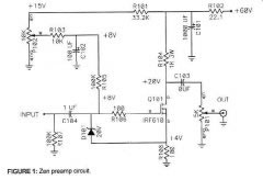
The preamp can also be used with other amplifiers, and can drive an impedance of 3k Ohms with ease. ���ǰ�÷Ŵ���Ҳ�������������ķŴ���,��������һ��3 kŷķ�迹�뻺�⡣As shown, frequency response is absolutely flat from 10Hz to 100kHz, without any frequency stabilisation required. ��ͼ��ʾ,Ƶ����Ӧ�Ǿ���ƽ��10���ȵ�100����,û���κ�Ƶ���ȶ�Ҫ��The table shows the rated performance of the gain module.�ϱ���ʾ�˶��������ģ�顣 #p#��ҳ����#e#Performance is almost identical to the original P37 published way back in 1999. �����Ǽ�����ͬ��ԭʼP37����1999����档The primary difference is that the new design can be used without any output capacitors, although I recommend that they be used anyway. ��Ҫ��������������ƿ����ڲ����κ��������,��Ȼ�ҽ�������������α�ʹ�á�Having any DC - even a few millivolts - across the volume pot will cause noise when the pot is rotated, and the caps ensure that this is eliminated. ���κ�DC -����������——��������ᵼ������������ת,ñȷ������������The main output coupling cap should be a bipolar (non-polarised) electrolytic, and the optional film bypass cap can be included if it makes you feel better (it won't affect frequency response though).��Ҫ��������ñӦ����һ��˫��(�Ǽ���)���,�Ϳ�ѡ�ĵ�Ӱ��·ñ���������������о����õ�(������Ӱ��Ƶ����Ӧ��Ȼ)�� Description���� The circuit for the left channel of the preamplifier module is shown in Figure 1, and as can be seen is very simple. �����·������������ǰ�÷Ŵ���ģ����ͼ1,���Կ����dz���The PCB is recommended, as it makes construction very straightforward. PCB���Ƽ���,��Ϊ��ʹ�����dz���This preamp relies on a completely hum free power supply, as it is not an integrated opamp, and cannot reject supply noise as well. ���ǰ�÷Ŵ���������һ����ȫ����ѹ���,��Ϊ������һ������opamp,Ҳ���ܾܾ���Ӧ������This is not to say that the power supply rejection is especially bad, just that it is not as good as an opamp.�Ⲣ����˵����������Ϊ���,����˵,������һ��opampһ���á�
Q2 and Q4 form a current source providing a bias current of about 7mA. Q2�͵��ļ��γɵ���Դ�ṩһ��ƫ�õ���Լ7����This stage is not an amplifier, but an active (and very linear) load, allowing the amplifying transistor Q3 to provide a high gain with excellent linearity. ����β���һ���Ŵ���,����һ����Ծ��(�ͷdz�����)����,�����Ŵ����Q3�ṩ����������ԶȺá�Feedback is applied through R6, with R5 setting the AC feedback ratio and thus the voltage gain of the amp. The transistors Q2 and Q3 operate at about 100mW and will get slightly warm in operation.������Ӧ��ͨ��R6,R5���ý�������ϵ������˵�ѹ�����amp������ܵڶ��͵�������Լ100����,����������ů�IJ����� The trimpot VR1 is used to set the voltage at the collectors of Q2 and Q3 to as close to zero volts as possible - this is easily measured at either end of R10. ���trimpot VR1�����趨��ѹ���ռ����ĵڶ��͵�������Ϊ�����ܽӽ������——����������������R10��Each amplifier has its own independent adjustment. ÿ���Ŵ��������Լ��Ķ����ĵ�����The bias current for each preamp module is bypassed to ground using C2 to help eliminate noise. Ϊÿ��ǰ�÷Ŵ�����ƫ�õ���ģ�����ƹ�����ʹ��C2��������������If you really don't want to use a multi-turn pot, there is provision on the PCB for a conventional horizontal mounting single-turn trimmer. �������IJ���ʹ�ö��,���ṩPCB�ϵĴ�ͳ��ʽ��װ��������This will make setting the 0V level more critical, but if the output caps are retained a small DC offset is not a problem. �⽫ʹ����0 vˮƽ����Ҫ,��������ñ�DZ���һ����С��ֱ��ƫ�Ʋ���һ�����⡣When the pot is adjusted for 0V at the collector of Q3, there will typically be around 4.7V across C2.��������Ϊ0 v�ڵ������ȵ��ղؼ�,ͨ��ԼΪ4.7 v��C2�� The distortion of the preamp is reasonably consistent with both output level and frequency, and is typically less than 0.01%. ǰ�÷Ŵ����ı������൱һ�µ������������Ƶ��,��ͨ������0.01%��I measured about 0.0075% - this is just above the residual of my signal generator (0.006%), so it is presumably much better than this, but I can't measure it. ������Լ0.0075%——�����Ը���ʣ����źŷ�����(0.006%),����������DZ������ø���,���Ҳ��ܲ�������A rough guess would be the difference between the two, giving 0.0015%, but I prefer to err on the side of caution. ���Թ��ƽ����ߵ�����,��0.0015%,���Ҹ�ϲ������ʧ֮������Noise is also extremely difficult to measure - there simply isn't enough of it to obtain an accurate reading with my equipment.����Ҳ���Ѻ���——��Ϊ����û���㹻���һ����ȷ���Ķ����ҵ��豸�� Frequency response is flat to within -0.1dB from 10Hz to 100kHz, and even at 100kHz, square wave performance is almost perfect, showing slight rounding and no ringing or instability of any kind. Ƶ����Ӧ��ƽ��,��-0.1 db��10���ȵ�100����,������100 khz,�������ܼ�����������,��ʾ��������Բ,û���κ���ʽ���������ȶ���Measured output impedance is 200 Ohms, and the circuit can drive 6 Volts RMS into a 3k Ohm load easily. ��������迹��200ŷķ,��·��������6��RMS��3 kŷķ���غ����ס�These are excellent figures, considering the simplicity of the circuit. ��Щ���dz�ɫ������,���Ǽĵ�·��The gain is nominally 3.2 (10dB) as shown, and is easily changed by varying R5 - increase the value to decrease gain and vice versa. �����ϵĻ����3.2(10�ֱ�)��ͼ��ʾ,�������ظı�ͨ���ı�——����ֵ���ӵ�R5��������,��֮��Ȼ��The PCB is 75 x 50mm, and has two complete amplifiers on the board.��PCB��75 x 50����,�����������ķŴ����ںڰ��ϡ� As many preamp modules as needed may be used. ������Ҫ�����ܶ��ǰ�÷Ŵ���ģ�����ʹ�á�For example, you may use one module before the volume control, and another after it to provide some additional gain and present a low impedance to the outside world. ����,������ʹ��һ��ģ������������,��һ�������ṩһЩ�������������ڵ�һ�����迹����������硣In many cases, the module will provide the only gain stage, and may be bypassed for high level signals (such as CD players) that have enough signal to drive the power amp directly. �����������,ģ�齫�ṩΨһ�������,�������ƹ���Ը�ˮƽ���ź�(��CD������),���㹻���ź��������ʷŴ���ֱ�ӡ�This is a great advantage for those who want the minimum number of components in line with the signal. ����һ���ܴ�����ƶ���Щ��Ҫ�����������������źš�The circuit cannot be direct coupled, however, since it has an inherent DC offset at the input. �����·����ֱ�����,Ȼ��,��Ϊ����һ�����ڵ�ֱ��ƫ�Ƶ����롣Polyester (or polypropylene if you must) caps can be used at the inputs, but for low impedance outputs, a bipolar electrolytic capacitors is recommended. ����(��۱�ϩ��������)ñ��������������,���Ƕ��ڵ��迹�����˫������������Ƽ��ġ�These may be bypassed with 100nF polyester caps, but the frequency response is not altered to any significant degree (not measurable at 100kHz), and there is no measurable decrease in distortion with the bypass caps.��Щ�������ƹ�100 nf����ñ,��Ƶ����Ӧ�Dz��ı��κ���Ҫ��(û�пɲ�����100ǧ��),����û�пɺ������½�����·ñ��Ť��
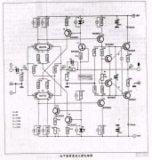
Figure 2 shows one channel of a suggested wiring for the preamp. ͼ2��ʾ��һ��Ƶ����һ������IJ���ǰ�÷Ŵ�����This is duplicated exactly for the other channel, and the switch and volume control are common to both. ������ȫ�ĸ�����������,���غ����������ǹ�ͬ�ġ�The CD input bypasses all electronics and is applied directly to the volume control, and the low level inputs use the gain of the modules to bring their level up to that of the CD player. CD�����ƿ����е��Ӻ���ֱ���������������,�͵�ˮƽ����ʹ�û�õ�ģ�齫���ǵ�ˮƽ��CD��������This introduces a bit more switching, but many audiophiles will prefer this method. �������˸���Ŀ���,���Ǻܶ���ѻ��ϲ�����ַ�����Note that when switched to CD, the input of the preamp is earthed to prevent any noise pick-up.ע��,���л���CD,�����ǰ�÷Ŵ����ǽӵص�,�Է�ֹ�κ�����ʰ������ The switching requires a 4-pole, 5 position rotary switch for both channels, and a dual-gang pot. I strongly suggest that a linear pot is used, with the resistor as shown. ������Ҫһ��,5��λ����ת������ͨ����һ��˫���ɹ�����ǿ�ҽ���ʹ��һ�����Թ�,��������ͼ��ʾ��Although this produces a variable impedance to the source, it is a better approximation of a log pot than those you can buy at normal outlets, and has much better tracking between channels. ����������һ���ɱ��迹Դ,����һ�����õĽ��Ƶ���־��������������������̵�,�и��õĸ���Ƶ��֮�䡣If you can get a conductive plastic logarithmic pot, do not use the resistor, as these are generally much better than the normal carbon film types, and the resistor will ruin the log curve.������ܵõ�һ���������϶�����,��Ҫʹ�õ�����,��Ϊ��Щͨ��Ҫ��������̼Ĥ����,�͵��������ٵ���־���ߡ� In some cases - due to an amplifier with unusually low input sensitivity for instance - an output gain stage might be needed. ��ijЩ�����,����һ���Ŵ����������Ѱ���ĵ���������������——һ���������ο�����Ҫ��This would typically use another gain module using the circuit above, but generally with lower gain. ��ͨ��ʹ����һ������ģ��ʹ�õ�·����,��ͨ���ϵ͵����档It is expected that a gain of 2 (6dB) will be enough for any amplifier, since this will provide an output of 4V RMS for a CD players typical 2V output. Ԥ������2(6�ֱ�)���������κηŴ���,��Ϊ�⽫�ṩһ�����4 v RMS����һ��CD���Ż����͵�2 v�����I have found that with typical sources, a preamp gain of about 10dB is sufficient to drive a typical power amplifier, so the additional gain will probably not be needed.�ҷ���,����͵���Դ,һ��ǰ�÷Ŵ�������Ĵ�Լ10�ֱ�����������һ�����͵Ĺ��ʷŴ���,��˶����ÿ��ܲ���Ҫ��
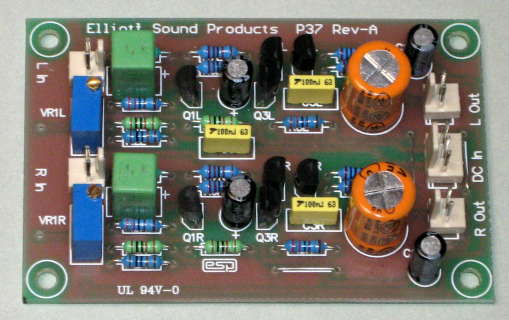
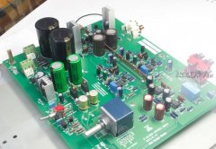
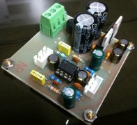
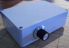
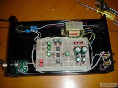
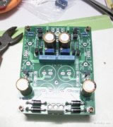
The photo shows what the new board looks like when fully populated according to the construction details.������Ƭ��ʾ���¶��»ῴ��������ȫ������ʩ��ϸ�ڡ� Power Supply��Դ The power supply must be free from hum and noise, and the circuit shown in Project 05 (Rev-B) is highly recommended. ������Ӧ������Ѻߺ�����,�͵�·��ʾ����Ŀ05(��b)�߶��Ƽ���A discrete circuit could also be used, but P05 is a far better proposition. һ����ɢ�ĵ�·Ҳ����ʹ��,����P05��һ�����õ����⡣The variable regulator ICs have extremely low noise. ����������ICs�м���������A single P05 will easily power about ten P37-A boards ... һ��P05�������ʴ�ԼʮP37-A���»�……more than anyone is likely to need.���κ��˶�������Ҫ�� (���α༭��admin) |